





Why Ceramic Parts Crack During Thermal Cycling
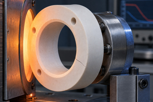
A ceramic part can operate below its published maximum temperature and still crack during heating or cooling. Maximum temperature describes only one material limit. Thermal-cycle survival also depends on how fast heat moves through the part, how freely the part can expand, where tensile stress concentrates, what defects are present, and how the ceramic is attached to other materials.
The first diagnostic question is therefore not "Was the furnace too hot?" It is "Where did the crack start, and what created tensile stress at that location?" A fracture surface, crack path, operating timeline, and assembly drawing usually provide more useful evidence than the peak temperature alone.
Thermal Gradients Create Stress Inside the Part
During rapid heating, the hot surface tries to expand before the cooler interior. During cooling, the surface may contract before the core. Because the regions remain connected, the temperature difference produces internal stress. Ceramics do not plastically yield like many metals, so a local tensile stress can extend an existing surface flaw into a crack.
Risk rises when a heat source is concentrated, the section is thick, thermal conductivity is low, cooling is uneven, or the cycle is too fast for the geometry. A thermocouple that records furnace air does not necessarily capture the temperature difference across the ceramic wall. Measure or model the part, especially near heaters, cold fixtures, gas jets, liquid contact, and shielded regions.
Geometry Often Determines Where Cracking Begins
Sharp internal corners, keyways, notches, blind holes, small edge ligaments, and abrupt wall changes raise local stress. We recommend avoiding stress concentrations, using chamfers or radii, and maintaining more uniform thickness where possible. These changes cannot eliminate thermal stress, but they reduce the peak stress at vulnerable features.
|
Observed crack location |
Likely contributors |
Useful checks |
|
Internal corner or slot end |
Small radius, machining damage, local stiffness change |
Radius, tool path, surface chips, crack origin under magnification |
|
Hole near an edge |
Thin ligament, fastener load, thermal gradient around the hole |
Edge distance, clamp force, washer contact, hole finish |
|
Thick to thin transition |
Different heating rates and constraint |
Temperature map, transition radius, section ratio |
|
Tube end or flange |
End restraint, impact damage, sealing load, cold fixture |
Mounting clearance, end chamfer, contact pattern, fixture temperature |
|
Metal ceramic interface |
CTE mismatch, braze or adhesive stiffness, asymmetric metal |
Material CTEs, joint thickness, voids, cycle range, residual bow |
|
Random surface origin |
Grinding damage, pore, inclusion, scratch, handling chip |
Fractography, surface-finish process, incoming inspection |
Fixtures Can Turn Expansion Into Tensile Load
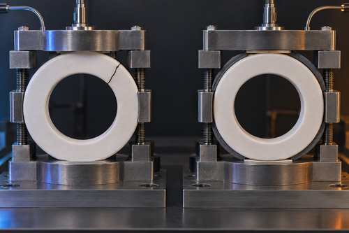
A ceramic component needs room to expand relative to a metal frame. A rigid clamp, metal interference fit, misaligned flange, or point contact can convert a modest temperature change into high local stress. Tightening torque applied at room temperature may also change as the fixture and ceramic expand at different rates.
- Check radial and axial clearance over the full temperature range.
- Use compliant layers or engineered joints where the design permits movement.
- Distribute clamp load over broad, flat contact areas instead of points or sharp metal edges.
- Avoid forcing a warped or out-of-flat ceramic against a rigid reference surface.
- Account for braze, solder, adhesive, and coating stiffness rather than comparing only bulk-material CTE values.
- Record assembly torque and sequence so repeat failures can be correlated with installation.
Material Choice Requires More Than Maximum Temperature
Thermal-shock resistance reflects several interacting properties, including strength, fracture toughness, elastic modulus, thermal expansion, thermal conductivity, surface condition, and component size. Published properties are usually measured on standardized specimens. They do not guarantee survival for a finished component with holes, joints, machining marks, or a steep temperature gradient.
|
Material direction |
Where it may help |
What still needs verification |
|
Alumina |
Electrical insulation, wear resistance, chemical stability, broad temperature capability |
Grade, purity, wall thickness, heating rate, and mounting; high temperature rating alone does not prevent thermal shock |
|
Silicon nitride |
High fracture toughness, strength, and resistance to rapid temperature change |
Grade-specific conductivity and oxidation environment; joining and machining details |
|
Silicon carbide |
High thermal conductivity, stiffness, wear resistance, and hot strength |
Manufacturing route, brittleness, surface flaws, oxidation, and joint design |
|
Aluminum titanate |
Very low thermal expansion and strong thermal-shock behavior in selected molten-metal applications |
Lower mechanical strength, microstructure, impact sensitivity, and chemical compatibility |
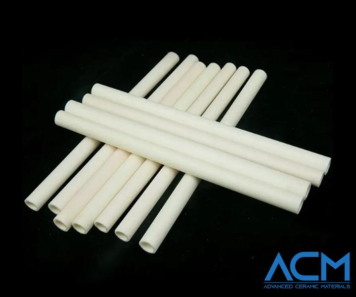
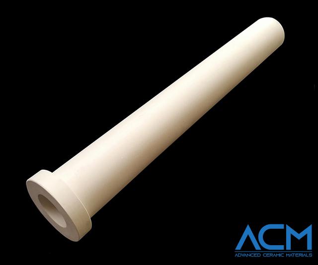
Examples of relevant product families include alumina tubes, silicon nitride tubes, silicon carbide plates, and aluminum titanate riser tubes. These links describe available materials and forms; final cycle limits must be confirmed for the grade, size, and assembly.
Surface Damage Can Control the Failure
Ceramic strength is flaw sensitive. Grinding grooves, edge chips, pores, inclusions, contact damage, and handling scratches can become fracture origins when thermal stress places them in tension. A smoother surface may improve reliability in a critical region, but polishing every face is not automatically the answer. The finishing direction, subsurface damage, edge preparation, and location of tensile stress matter.
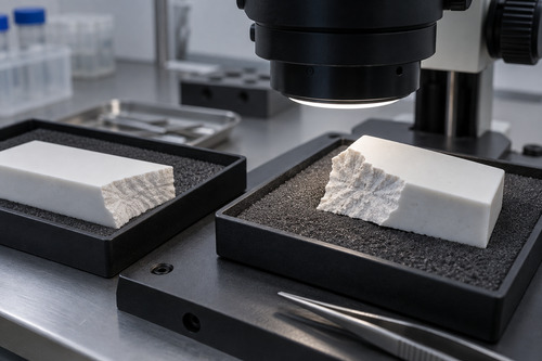
When a failed part is available, preserve the pieces and the fracture surface. Do not rub the mating faces together or aggressively clean them. NIST's fractography guide explains how fracture markings can identify the origin and distinguish processing defects, surface damage, impact, and service loading. This evidence is much stronger than assuming the material batch was defective because a crack appeared.
Build a Failure Timeline
- Record whether the part failed during initial heat-up, steady operation, cooldown, restart, cleaning, or disassembly.
- Collect the programmed temperature profile and the measured temperatures near the ceramic and fixtures.
- Map the crack before removing the part, including its position relative to heaters, supports, holes, joints, and gas flow.
- Record assembly torque, preload, gasket condition, adhesive or braze lot, and any evidence of contact or impact.
- Compare the failed part with prior successful parts for material grade, dimensions, surface finish, wall thickness, and process history.
- Examine the fracture origin before changing multiple variables at once.
Changing the ramp rate, material, thickness, and fixture simultaneously may stop the failure, but it does not reveal which change solved it. A controlled trial should address the most likely mechanism first and retain enough instrumentation to confirm the result.
Corrective Actions by Failure Mechanism
|
Mechanism |
Possible corrective actions |
|
Excessive thermal gradient |
Reduce ramp rate; preheat; shield direct radiation; distribute the heat source; reduce section thickness where mechanically acceptable; prevent cold gas or liquid impingement |
|
Stress concentration |
Increase internal radius; add edge chamfers; move holes away from edges; use gradual thickness transitions; remove unnecessary notches |
|
Assembly restraint |
Increase clearance; reduce or control preload; use compliant joints; improve fixture alignment; distribute contact pressure |
|
CTE mismatch |
Change mating material or joint design; adjust joint thickness and compliance; reduce asymmetric metal coverage; validate the full stack |
|
Machining or handling damage |
Improve edge protection; revise grinding and lapping steps; inspect critical tensile surfaces; redesign packaging and assembly tools |
|
Material mismatch |
Select a grade with a more suitable combination of conductivity, expansion, strength, and toughness; confirm chemical and electrical requirements remain satisfied |
Information to Send the Supplier
- Part drawing, material grade, lot number, and manufacturing or purchase date
- Photographs of the installed part and crack before removal
- Heating and cooling profile, cycle count, dwell time, and measured part temperatures
- Atmosphere, pressure, gas flow, chemicals, molten materials, and cleaning method
- Fixture drawing, mating materials, clearances, torque, preload, and joining materials
- Fracture pieces protected from contact, plus microscopy or inspection results if available
- Any difference between the failed run and the last successful run
For a material or design review, submit this information with the component drawing through the ACM inquiry form. A photograph alone may show where the part separated, but the temperature and fixture history are usually needed to explain why.
Conclusion
Thermal-cycle cracking is a system failure involving temperature distribution, geometry, surface condition, and restraint. Start with the crack origin and operating timeline. Then correct the mechanism that created tensile stress. This produces a more reliable solution than choosing a ceramic only from maximum operating temperature or replacing the same part without changing its environment.

{{item.content}}
LEVE A REPLY
{{item.children[0].content}}
{{item.content}}
LEAVE A REPLY
SUBSCRIBE OUR NEWSLETTER

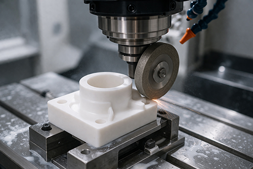 Ceramic Machining: Essential Techniques and Processes for Precise Components
This article explains ceramic machining in plain language. It covers how ceramic items are produced, the role of machining in shaping these products, and methods such as grinding, milling, and CNC machining.
READ MORE >
 Alumina Powder (Al2O3): A Technical Guide to Grades, Properties, and Applications
How to choose alumina powder purity from 92% to 99.99%. ACM guide covers decision tree, properties, ZTA, and application tables for engineers.
READ MORE >
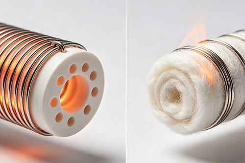 Ceramic Heating Coil Versus Cotton Coil: Choosing the Better Fit
When people compare a ceramic heating coil with a cotton coil, the real question is usually not "which one is better on paper?" It is "which one makes life easier in daily use?" In practice, that comes down to heat control, maintenance, lifespan, and how often you want to swap parts or deal with burnt taste.
READ MORE >