




Ceramic-to-Metal Brazing Guide for Custom Assemblies
Step 1: Does the joint actually need brazing?
An RFQ for an alumina ring joined to a metal flange may include complete dimensions and still leave the most important question unanswered: what must the joint do?
Brazing is normally considered when the ceramic and metal must form a permanent assembly that withstands heat, maintains electrical isolation, carries a mechanical load, or provides a vacuum or gas seal. It is less attractive when the assembly must be removed regularly or when an adhesive or mechanical clamp can meet the temperature, cleanliness, and sealing requirements.
|
Assembly requirement |
Initial direction |
|
Permanent hermetic or vacuum seal |
Brazing is a strong candidate |
|
High-temperature electrical insulation |
A brazed ceramic-to-metal assembly may be suitable |
|
Removable ceramic component |
Consider clamping or another mechanical joint |
|
Low-temperature, non-hermetic attachment |
Adhesive bonding may be sufficient |
|
Large ceramic panel attached across its full face |
Review thermal expansion before choosing brazing |
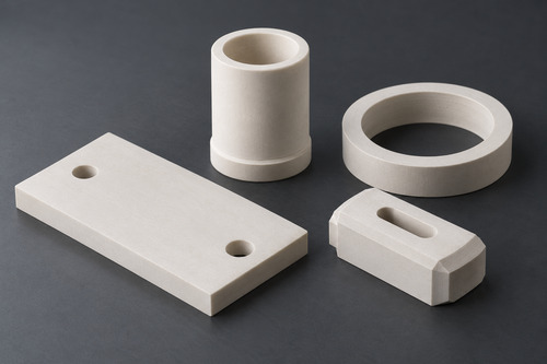
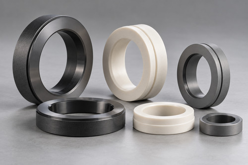
For assemblies built around alumina, ACM's custom alumina parts can be produced with joining surfaces, edge geometry, and tolerances defined for later metallization or brazing. These requirements should be identified before the ceramic enters production.
Record the required function before selecting the ceramic or braze alloy. "Attach ceramic to metal" is not enough. The specification should state whether the joint is structural, electrically insulating, thermally conductive, hermetic, or some combination of these.
Step 2: Which ceramic and metal belong in the same assembly?
The ceramic and metal should be evaluated as a pair. A material that performs well by itself may become difficult to use when joined to a second material and cooled from the brazing temperature.
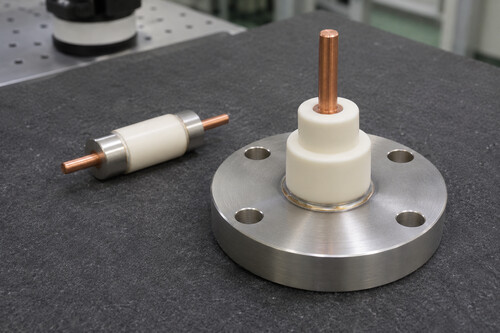
Alumina is often the first ceramic considered for electrical feedthroughs, vacuum insulators, sensor housings, and high-temperature seals. It combines electrical insulation with dimensional stability and is available in grades compatible with established metallization processes.
Aluminum nitride is worth considering when heat must pass through the ceramic while electrical isolation is maintained. Its higher thermal conductivity can be useful in power electronics and heat-removal assemblies, but its surface preparation, metallization, and metal pairing require separate review. A process developed for alumina should not automatically be transferred to AlN.
The metal should be identified by exact alloy and condition. "Stainless steel" or "nickel alloy" leaves too much undefined. The coefficient of thermal expansion, yield behavior, thickness, and stiffness of the selected metal all influence the stress transferred into the ceramic.
A low-expansion iron-nickel-cobalt alloy may be considered for an alumina seal because its expansion behavior is closer to that of the ceramic than many common structural metals. This does not make every alumina–low-expansion alloy joint safe. Section thickness and joint geometry can still create damaging tensile stress.
Use these screening rules:
-
Start with alumina where electrical insulation and an established hermetic-sealing route are the main requirements.
-
Consider AlN where heat removal through the insulating ceramic is a central requirement.
-
Avoid pairing a thin ceramic directly with a large, rigid metal mass without stress analysis or design review.
-
If the expansion difference is substantial, give the metal section enough compliance to deform without pulling the ceramic apart.
-
Record the exact ceramic grade and metal alloy before the brazing process is approved.
Step 3: Pre-metallization or active-metal brazing?
The two main process routes solve the ceramic wetting problem differently.
Pre-metallized ceramic
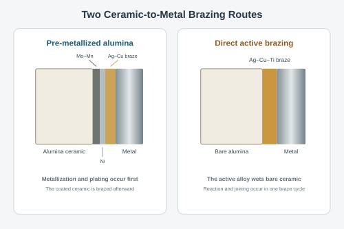
A metallization layer is fired onto the ceramic before the final joint is brazed. Alumina assemblies commonly use a refractory-metal metallization system followed by nickel plating and brazing, although the exact coating stack depends on the ceramic grade and the approved process.
This route is generally worth considering when:
-
the project uses alumina and an established ceramic-seal process;
-
the ceramic will be plated, soldered, or brazed in a later operation;
-
the customer needs a clearly defined metal layer on selected ceramic surfaces;
-
metallized ceramic parts and final brazing will be handled by different suppliers or production stages.
Active-metal brazing
An active braze alloy contains a reactive constituent, often titanium, that enables the alloy to interact directly with the ceramic surface. This can eliminate a separate pre-metallization operation.
Active brazing is generally worth considering when:
-
a direct ceramic-to-metal brazing route is preferred;
-
the ceramic is not suited to the established pre-metallization process;
-
the assembly geometry can be fixtured and brazed in a controlled vacuum or inert atmosphere;
-
the reaction layer, alloy volume, clearance, and thermal cycle can be closely controlled.
|
Decision point |
Pre-metallization route |
Active-metal brazing |
|
Separate coating operation |
Required |
Usually not required |
|
Direct wetting of bare ceramic |
No |
Yes |
|
Established alumina seal process |
Often a practical choice |
Possible, but process review is needed |
|
Later plating or soldering |
Often easier to integrate |
Surface system must be reviewed |
|
Control of reactive interfacial layer |
Not the primary mechanism |
Critical |
Do not choose between the routes from part quantity alone. Ceramic type, joint geometry, existing production equipment, surface requirements, and the operations performed after brazing usually matter more.
Step 4: What happens when the joint cools?
The assembly is nearly stress-free at the brazing temperature. Stress develops during cooling because the ceramic, metal, and braze alloy do not contract by the same amount.
Ceramics tolerate compressive loading better than tensile or peeling loads. Joint geometry should therefore avoid pulling directly on a ceramic edge or forcing a thin ceramic section to follow the contraction of a much thicker metal part.
Several warning signs can be identified from the drawing:
-
A large rigid metal plate brazed across a thin ceramic face: the metal may dominate contraction and place the ceramic in tension.
-
A braze boundary ending at a sharp ceramic corner: stress can concentrate where the joint and corner meet.
-
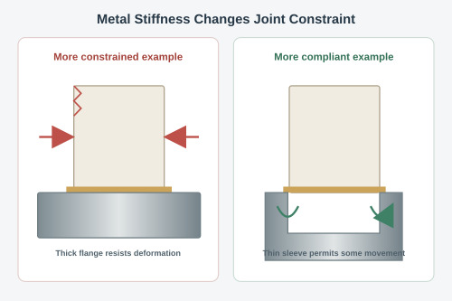
A thick metal flange around a thin ceramic tube: the ceramic may be strongly constrained during cooling.
-
An uncontrolled braze gap: alloy distribution, void formation, and joint stiffness may vary from part to part.
-
A load applied as peeling or bending: the joint may fail at a much lower force than under axial compression.
A thin metal sleeve or another compliant metal feature can sometimes absorb differential contraction more effectively than a thick, rigid flange. A radius or relief near the ceramic edge may also reduce local stress. These features must be evaluated with the actual dimensions; simply changing the material name will not correct a poor joint shape.
More braze alloy is not automatically safer. Excess alloy changes the fillet, joint stiffness, and residual-stress distribution. Show the intended joint clearance and alloy location rather than leaving the entire interface as an undefined volume.
Step 5: What belongs on the ceramic drawing?
The joining surface needs its own requirements. A general note such as "surface smooth" does not define a surface for metallization or brazing.
Identify the following on the ceramic detail:
-
surface to be metallized or directly brazed;
-
metallization boundary and keep-out area;
-
dimensions that apply before metallization;
-
dimensions that apply after plating or brazing;
-
flatness and parallelism of the joining surface;
-
required surface finish;
-
edge radius, chamfer, or edge-break requirement;
-
areas that must remain electrically insulating;
-
surfaces that must remain free of braze alloy;
-
cleanliness and packaging requirements.
If metallization must stop before a sealing face or creepage path, dimension that boundary. Do not rely on a production operator to infer it from the appearance of the part.
Grinding damage and edge chips close to the joint can become crack origins during brazing or later thermal cycling. Functional joining surfaces should therefore have separate acceptance criteria from ordinary cosmetic surfaces.
For components supplied with an applied metal layer, ACM's metal-coated ceramic substrates illustrate the range of ceramic and metal surface combinations available. A custom drawing should still define the coating material, stack, pattern, thickness, keep-out zones, and intended joining operation.
Step 6: What will count as a passing joint?
Start from the function identified in Step 1. A mechanically attached bracket and a hermetic electrical feedthrough do not need the same test plan.
|
Joint function |
Possible acceptance checks |
|
Mechanical attachment |
Dimensions, visual condition, pull or shear test on qualification samples |
|
Vacuum or gas seal |
Helium leak test with a stated method and limit |
|
Electrical insulation |
Insulation resistance, dielectric test, creepage and metallization inspection |
|
Thermal-cycling service |
Leak, electrical, or mechanical test before and after a defined cycle schedule |
|
Critical internal joint quality |
Radiography, cross-section analysis, or another agreed qualification method |
"Hermetic" should be replaced by a measurable requirement. State the test gas, method, maximum leak rate, test condition, and whether testing occurs before or after thermal cycling. For small sealed packages, internal volume and test timing can affect interpretation of the result.
Visual inspection remains useful for finding cracks, excess alloy, incomplete fillets, contamination, and obvious metallization defects. It cannot prove that an internal joint is void-free or that a sealed assembly meets its leak limit.
Separate qualification testing from routine production inspection. Cross-sectioning, destructive pull testing, and extended thermal cycling may be appropriate for process qualification or witness samples without being performed on every production unit.
Step 7: Is the RFQ complete?
Before requesting a quotation, confirm that the package contains:
-
complete assembly drawing;
-
separate ceramic and metal detail drawings;
-
ceramic material, grade, and purity;
-
metal alloy and condition;
-
required joining route, if already approved;
-
restricted or prohibited braze-alloy elements;
-
metallized areas and braze keep-out regions;
-
joint clearance and critical alignment dimensions;
-
operating atmosphere and pressure;
-
minimum and maximum service temperatures;
-
heating and cooling rates;
-
expected thermal-cycle count;
-
mechanical and electrical loads;
-
leak-test method and acceptance limit;
-
operations performed after brazing, including plating or welding;
-
qualification tests and production acceptance checks;
-
prototype and production quantities.
If the brazing route has not been fixed, provide the functional requirements instead of assigning an alloy or metallization system without supporting process data. This gives Advanced Ceramic Materials (ACM) enough information to review the ceramic grade, joining surface, joint geometry, and inspection requirements together.
Before the drawing is released
The ceramic and metal should not be designed as two independent parts that happen to meet at a braze line. Their expansion behavior, stiffness, interface geometry, and production sequence create one assembly.
A final drawing review should answer four questions:
-
Does the application actually require a brazed joint?
-
Can the selected ceramic and metal tolerate the brazing and cooling cycle?
-
Are the joining surfaces, clearances, and keep-out areas fully defined?
-
Can the finished joint be accepted using a measurable test?
If any answer is unclear, resolve it before the ceramic enters production. Changing a joining surface or edge geometry at the drawing stage is usually more practical than reworking a finished ceramic component that cannot be metallized or brazed as intended.
References
-
A. Levy, "Thermal Residual Stresses in Ceramic-to-Metal Brazed Joints," Journal of the American Ceramic Society, 74(9), 2141–2147 (1991). https://doi.org/10.1111/j.1151-2916.1991.tb08273.x
-
B. Mann, K. Ford, M. K. Neilsen, and D. Kammler, "Minimizing Residual Stress in Brazed Joints by Optimizing the Brazing Thermal Profile," ASME IMECE (2020). https://doi.org/10.1115/IMECE2020-24618
-
MIL-STD-883, Method 1014, "Seal," U.S. Department of Defense.

{{item.content}}
LEVE A REPLY
{{item.children[0].content}}
{{item.content}}
LEAVE A REPLY
SUBSCRIBE OUR NEWSLETTER
 Aluminum Nitride Ceramic Selection Guide for Custom Parts
A practical guide to grade selection, thermal design, machining, surface requirements, handling, and incoming inspection
READ MORE >